Mastering Oscilloscope Triggers and Capture
2026-03-11 | By Zach Hipps
In the first oscilloscope post, I focused on helping beginners overcome that initial intimidation, because when you turn one of these on for the first time, it really does feel like you are staring at the control panel of a spaceship. The response was awesome. A lot of you said it finally helped things click, but you also left a lot of really good follow-up questions. Things like, can you explain triggering a little more in detail? How do I capture signals that are not periodic, and what do I do if I want to capture multiple signals? My name is Zach, and I am The Byte Sized Engineer. In this post, I am going to help you feel less like a confused astronaut and more like a confident engineer who knows how to use an oscilloscope.

Just a quick recap: we use oscilloscopes to see and troubleshoot invisible problems. Sometimes we use a multimeter to measure a voltage that remains constant over time, but when our signal is changing, especially when it is changing quickly, that is when an oscilloscope really comes in handy. We also discussed the three characteristics that differentiate oscilloscopes: the number of channels, bandwidth, and sampling rate. To help us dive deeper into this topic, I am using the Rigol DHO924S. It has a ton of upgrades: it is super thin, powered by USB-C, has a touchscreen interface, and runs Android. This scope even adds a logic analyzer probe and a function generator.

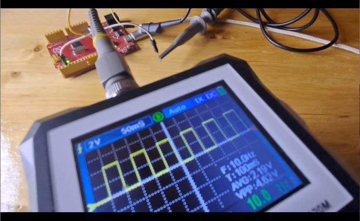
Many of the questions I received revolved around triggering. When you are capturing a signal, and it just does not look quite right, it is often your trigger settings that need adjusting. To show you what I mean, let’s look at an electronic drum trigger. Inside, it is basically just a couple of piezo elements. If I connect the ground clip to one wire and the probe to the other on the drum trigger, when I strike the piezo element, I see a waveform, but I don't get a clear view of each waveform because the trigger isn't set correctly. Right now, we are triggering on a falling edge, but there are other options, such as pulse, slope, video, pattern, duration, timeout, and others. You do not need to master all of these, but they help when an edge trigger fails. For example, if I use a slope trigger, I can choose my source and filter out all signals except those with a slope greater than a certain threshold. If I only care about sharp, staccato attacks on this drum trigger, I can set a short time duration to filter out long, slow signals. This leads to another common question: What is the difference between single capture and continuous capture? When a signal repeats or is periodic, use continuous capture, but our drum signal is not predictable. I have to tap it manually. In this case, we use a single capture. The oscilloscope patiently waits until the specific trigger conditions are met, then freezes the event on the screen.


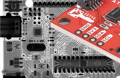
Let’s look at another type of triggering. I have a microcontroller connected to two I2C devices: a GPIO expander and a proximity detector. On the screen, the yellow and blue waveforms are wandering, indicating incorrect triggering. Instead of triggering on a slope, we can trigger on the I2C protocol itself. I have channel one on the clock and channel two on the data. I2C has conditions like start and stop, but triggering on an address is one of the most useful methods. Since multiple devices share the same bus, each device has a unique address. One cool thing about this scope is that it can decode these signals. I can see we are writing to the device at address 0x60 (the proximity sensor) and address 0x20 (the GPIO expander). If I only want to see communication for the expander, I go into the trigger settings, select address as my trigger, and set it to hex 0x20. Now the scope filters out everything else. I can even pull up an event table to see the timing and data for every event. This is critical for finding bugs in complex projects.


Beyond the basics, we have the logic analyzer. Most of the time, this is a separate device, but this scope has one built in. I used a logic analyzer to debug my XRP robotic platform, which includes a microcontroller communicating with an ESP32 and a spinning LiDAR sensor. There is a lot of communication happening at once. I had to do a lot of debugging to get the project to work. I plugged the logic analyzer into the front and connected probes to the serial TX and RX signals. Since the LiDAR starts scanning automatically, it just spits data out on the receive line. I can use the same triggering and decoding methods here as I did with the analog probes to see exactly what the LiDAR is telling the robot.


Finally, let’s look at a brushless DC motor from a DIY drone. It has three-phase wires, and I want to see their relationship. To see all three phases interact, I connect a 10k resistor to each phase, then connect the three resistors to a common node to serve as a reference point. I then connect three oscilloscope probes to the phase wires. When I spin the motor, all three windings produce a sinusoidal wave. If I spin it with a drill, I can see that as the speed increases, both the frequency and the amplitude increase. All three sinusoidal waves are perfectly out of phase by 120 degrees.


Hopefully, this helped demystify some of the intimidating parts of the oscilloscope. Do not worry about mastering every feature at once. Start simple and work your way up as your projects get more complicated. The more specific you are about what you want to see, the more powerful this tool becomes.