Les progrès réalisés dans les domaines de la détection, de la connectivité et du contrôle des mouvements permettent de créer des robots à poste fixe plus intelligents
Avec la contribution de Rédacteurs nord-américains de DigiKey
2025-11-18
Les systèmes robotiques montés (à poste fixe), souvent appelés robots multi-axes, sont conçus pour effectuer des mouvements de haute précision et hautes performances à l'intérieur d'un espace de travail défini. Ces systèmes constituent l'épine dorsale des cellules de fabrication et d'automatisation modernes, où la reproductibilité, la vitesse et la capacité de charge sont essentielles.
Parmi les exemples les plus courants, citons les robots collaboratifs (cobots), les bras des robots articulés, les bras des robots articulés à conformité sélective (SCARA) et les mécanismes delta (à liaisons parallèles), ainsi que les machines à commande numérique par ordinateur (CNC) et les machines de type portique. Selon les exigences de l'application, ces robots peuvent être montés sur des rails, des murs, des plafonds, des sols ou intégrés directement dans des machines de production, ce qui permet un déploiement flexible pour les processus d'assemblage, de manutention, de conditionnement, d'inspection et d'usinage.
En combinant une électronique d'entraînement moderne, des capteurs de précision et des architectures de contrôle en temps réel, ces plateformes robotiques montées offrent la fiabilité, la polyvalence, la fonctionnalité et la précision indispensables aux environnements de fabrication intelligents et connectés. Toutefois, pour optimiser les avantages et les performances de ces systèmes, les concepteurs doivent comprendre et appliquer les dernières avancées en matière de détection de mouvement, de position et de zone, de contrôle de mouvement et de connectivité.
Cet article examine brièvement les exigences de conception des robots modernes. Il présente ensuite des exemples de solutions et des kits d'évaluation connexes d'Analog Devices que les concepteurs peuvent utiliser pour mettre en œuvre ces systèmes.
Exigences de conception des robots avancés
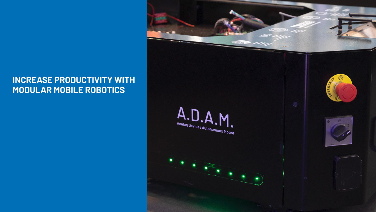
Les robots montés modernes (Figure 1) se distinguent des robots mobiles à deux égards : ils opèrent dans un environnement global relativement statique et connu, et ils ne sont pas limités par l'autonomie de leur batterie. Cependant, ils sont censés fonctionner avec rapidité, précision, répétabilité et exactitude en dépit de circonstances changeantes. Par exemple, ils peuvent être amenés à saisir des boîtiers de tailles, de formes, d'orientations, de positions et de poids différents, puis à les placer à un endroit précis sur un tapis roulant. Pour ce faire, ces robots doivent évaluer la situation de manière autonome et s'y adapter de manière dynamique, tout en restant conscients de leurs paramètres et de leur environnement.
 Figure 1 : Ce robot à poste fixe, bien connu et largement répandu, offre désormais une précision, une flexibilité et une adaptabilité exceptionnelles. (Source de l'image : Analog Devices Inc.)
Ces exigences nécessitent l'intégration minutieuse d'un contrôle précis des mouvements pour les effecteurs terminaux, d'une imagerie à temps de vol (ToF) pour la perception de l'environnement, d'unités de mesure inertielle (IMU) pour la détection des mouvements et d'une liaison GMSL (Gigabit Multimedia Serial Link) pour une communication fiable et à haute vitesse.
1 : Contrôle de mouvement pour les préhenseurs des effecteurs terminaux : Les préhenseurs des robots fonctionnent comme des mains ou des pinces, s'ouvrant et se fermant à la demande. Ils doivent exercer une force appropriée pour maintenir une prise ferme sans endommager la charge utile. Pour ce faire, l'entraînement du moteur doit commander le moteur avec précision afin d'assurer un fonctionnement précis, régulier et fluide. L'entraînement doit également être léger et compact en raison des contraintes de poids et d'espace.
La servocommande à axe unique TMCM-1617 (Figure 2) est une solution adaptée à ce type de contrôleur. Pesant 24 g et mesurant 36,8 mm × 26,8 mm × 11,1 mm, cet entraînement de moteur CC sans balais (BLDC) triphasé peut fournir jusqu'à 18 A RMS et fonctionne à partir d'une alimentation de 8 V à 24 V.
") Figure 2 : Légère et compacte, la servocommande TMCM-1617 offre une commande complète de moteur BLDC de 8 V à 24 V, 18 A. (Source de l'image : Analog Devices Inc.)
Figure 2 : Légère et compacte, la servocommande TMCM-1617 offre une commande complète de moteur BLDC de 8 V à 24 V, 18 A. (Source de l'image : Analog Devices Inc.)
Le TMCM-1617 prend en charge les codeurs incrémentaux et les capteurs numériques à effet Hall pour le retour d'information sur la position, ce qui améliore sa précision et sa répétabilité sous des charges variables. En matière de connectivité, il dispose d'options de bus CAN, RS-485 et EtherCAT.
Pour évaluer et régler rapidement le TMCM-1617 et ses algorithmes, Analog Devices propose la conception de référence du préhenseur TMCM-1617-GRIP-REF. Cette conception de référence matérielle open-source est spécialement conçue pour la commande précise des moteurs BLDC de 24 V utilisés dans les préhenseurs robotiques. Elle fournit un contrôle vectoriel (FOC) précis, garantissant une ondulation minimale du couple et permettant une commande efficace et performante du moteur. La pile logicielle préconfigurée simplifie le processus d'installation initiale, réduisant ainsi les délais de mise sur le marché.
2 : Capteurs ToF : Les concepteurs disposent de deux options de base pour s'assurer que le robot est pleinement conscient de son environnement et de tous les objets se trouvant dans sa zone d'action : utiliser un dispositif de détection ToF ou utiliser une ou plusieurs caméras vidéo. Chacune de ces options présente des avantages et des inconvénients relatifs.
En général, les caméras ToF sont privilégiées pour la détection de la profondeur et offrent une mesure de distance très précise. Toutefois, leur résolution spatiale est généralement inférieure à celle des caméras vidéo classiques et elles peuvent être affectées par la lumière ambiante et les surfaces réfléchissantes. Les caméras vidéo standard, quant à elles, fournissent des images à haute résolution et sont polyvalentes pour diverses applications, mais l'extraction d'informations de profondeur nécessite un traitement plus complexe et plusieurs caméras.
Pour de nombreuses applications robotiques, les avantages de l'imagerie ToF sont considérables. Un sous-système de détection basé sur la technologie ToF nécessite toutefois l'intégration minutieuse de nombreux composants électro-optiques, notamment une source lumineuse LED adaptée, des lentilles, des filtres optiques et un imageur. La sélection et l'assemblage de ces composants requièrent des connaissances approfondies en électricité, en mécanique et en optique.
Pour minimiser ces difficultés, Analog Devices propose le module ToF ADTF3175 (Figure 3). Cette unité complète fonctionne avec un imageur ToF indirect CMOS de 1 mégapixel (MP). Elle intègre également une lentille et un filtre passe-bande optique de 940 nm pour l'imageur, une source d'éclairage infrarouge contenant des éléments optiques, une diode laser, un circuit d'attaque de diode laser et un photodétecteur, une mémoire Flash et des régulateurs de puissance afin de générer des tensions d'alimentation locales.
") Figure 3 : Le module ADTF3175 comprend tous les éléments électroniques, mécaniques et optiques nécessaires à un sous-système ToF complet. (Source de l'image : Analog Devices Inc.)
Figure 3 : Le module ADTF3175 comprend tous les éléments électroniques, mécaniques et optiques nécessaires à un sous-système ToF complet. (Source de l'image : Analog Devices Inc.)
Les données issues du cloud d'images du capteur ADTF3175 de 1024 × 1024 pixels (avec un champ de vision (FOV) de 75° × 75°) sont envoyées au système hôte via une interface MIPI CSI-2 à quatre voies fonctionnant à 1,5 gigabit par seconde (Gbps) par voie. La programmation et le fonctionnement du module sont contrôlés par une interface périphérique série (SPI) à quatre fils et une interface I2C. La plage de profondeur est comprise entre 0,4 et 4 mètres (m) avec une précision de ±5 mm sur toute la plage de profondeur.
Un processeur de signaux d'image de profondeur ADSD3500 associé convertit les données brutes en mégapixels provenant de l'ADTF3175 afin de produire des trames de données finales pour la profondeur radiale, la luminosité active (AB) et la confiance. Cela garantit une faible latence avec des fréquences d'images élevées et permet à la caméra de capturer avec précision des objets en mouvement rapide et au robot de prendre des décisions opportunes et de fournir des analyses précises dans des environnements industriels en constante évolution.
Pour faciliter la configuration et la mise en œuvre du module, Analog Devices propose le kit d'évaluation du capteur 3D ToF EVAL-ADTF3175D-NXZ (Figure 4). Ce kit open-source comprend le module ADTF3175, une unité de traitement numérique tierce pour les applications embarquées d'intelligence artificielle (IA) et d'apprentissage automatique (ML), une carte d'interface de caméra, une carte d'adaptateur interposeur et un trépied.
 Figure 4 : Le kit d'évaluation EVAL-ADTF3175D-NXZ fournit le traitement, les connecteurs et le trépied nécessaires pour faciliter l'intégration du capteur ToF ADTF3175. (Source de l'image : Analog Devices Inc.)
3 : IMU (unité de mesure inertielle) : Comme l'effecteur terminal (préhenseur) du robot est libre de se déplacer n'importe où dans la zone tridimensionnelle qui lui est réservée, il est essentiel de connaître à la fois sa position et son orientation dans cet espace. Une façon d'y parvenir consiste à utiliser des codeurs à chaque articulation, puis à combiner toutes leurs sorties en utilisant une transformation de coordonnées et des équations matricielles. Toutefois, cette méthode nécessite plusieurs codeurs multi-axes et ajoute à la complexité des calculs.
Une alternative intéressante consiste à utiliser une IMU à six degrés de liberté (6 DoF) qui combine un accéléromètre à trois axes (triaxial) et un gyroscope à trois axes. L'IMU MEMS (microsystèmes électromécaniques) miniature ADIS16500 (Figure 5, à gauche) offre cette fonctionnalité dans un minuscule boîtier de 15 mm × 15 mm× 5 mm doté d'une sortie SPI. La carte d'évaluation ADIS16500/PCBZ associée (Figure 5, à droite) mesure 33,25 mm × 30,75 mm. Cette carte sert principalement de carte Breakout pour faciliter les connexions de câblage via un connecteur à 16 broches (2 × 8), à pas de 2 mm, au système d'évaluation complet EVAL-ADIS2Z.
") Figure 5 : Le schéma fonctionnel de haut niveau de l'ADIS16500 (à gauche) ne donne qu'un aperçu de l'intégration interne et de la sophistication de cette unité IMU 6-DoF ; la carte Breakout ADIS16500/PCBZ associée (à droite) sert principalement d'interface de connexion physique au système d'évaluation EVAL-ADIS2Z. (Source de l'image : Analog Devices Inc.)
Figure 5 : Le schéma fonctionnel de haut niveau de l'ADIS16500 (à gauche) ne donne qu'un aperçu de l'intégration interne et de la sophistication de cette unité IMU 6-DoF ; la carte Breakout ADIS16500/PCBZ associée (à droite) sert principalement d'interface de connexion physique au système d'évaluation EVAL-ADIS2Z. (Source de l'image : Analog Devices Inc.)
Les gyroscopes numériques offrent une plage dynamique de ±2000° par seconde (˚/s), contre ±392 m/s2 pour les accéléromètres numériques. Chaque capteur inertiel de la gamme ADIS16500 comprend une mise en forme des signaux qui optimise les performances dynamiques.
En outre, comme les gyroscopes et les accéléromètres présentent des sources d'erreur inhérentes spécifiques, l'étalonnage en usine est utilisé pour caractériser chaque capteur en termes de sensibilité, de polarisation, d'alignement, d'accélération linéaire (polarisation du gyroscope) et de point de percussion (emplacement de l'accéléromètre). En conséquence, chaque capteur dispose de formules de compensation dynamique qui permettent d'obtenir des mesures extrêmement précises du capteur dans un large éventail de conditions.
4 : GMSL : La réunion de tous ces blocs fonctionnels dans un bras robotique doit tenir compte de considérations importantes : ils doivent être reliés entre eux et, en particulier pour le module ToF, ils génèrent une grande quantité de données sensibles au facteur temps. L'interface GMSL répond à ces problématiques. Développée à l'origine pour l'industrie automobile, la technologie GMSL a été adoptée par des applications telles que la robotique, car elle permet d'atteindre les débits de données élevés requis sur un seul câble.
Par exemple, le désérialiseur MAX96724, conditionné dans un boîtier TQFN de 8 mm × 8 mm, convertit quatre entrées GMSL 2/1 en 1, 2 ou 4 chemins MIPI D-PHY ou C-PHY (Figure 6). Ce dispositif de 6 Gbps, à quatre entrées et deux sorties, permet des transmissions bidirectionnelles simultanées sur des câbles coaxiaux de 50 ohm (Ω) ou des câbles blindés à paire torsadée (STP) de 100 Ω. Il peut prendre en charge jusqu'à quatre capteurs distants.
") Figure 6 : Le désérialiseur MAX96724 convertit quatre entrées GMSL 2/1 en 1, 2 ou 4 chemins MIPI D-PHY ou C-PHY. (Source de l'image : Analog Devices Inc.)
Figure 6 : Le désérialiseur MAX96724 convertit quatre entrées GMSL 2/1 en 1, 2 ou 4 chemins MIPI D-PHY ou C-PHY. (Source de l'image : Analog Devices Inc.)
Chaque liaison série GMSL2 fonctionne à un débit fixe de 3 ou 6 Gbps dans le sens direct et de 187,5 Mbps dans le sens opposé. La liaison peut également adapter automatiquement les caractéristiques du récepteur sur le trajet direct pour compenser les pertes d'insertion et les pertes par réflexion du canal ; ces pertes sont largement déterminées par les câbles, les connecteurs, les effets de la température et les propriétés de la carte à circuit imprimé. Le MAX96724 prend à la fois en charge l'agrégation et la réplication des données vidéo, ce qui permet de combiner les flux provenant de plusieurs capteurs distants.
Ces dispositifs sont complexes à installer et à utiliser. Grâce au kit d'évaluation MAX96724-BAK-EVK#, Analog Devices simplifie cette tâche (Figure 7). Ce kit fournit une conception éprouvée et une plateforme fiable pour l'évaluation des dispositifs MAX96724 à l'aide de câbles coaxiaux FAKRA standard (assemblage câble/connecteur robuste utilisé dans l'industrie automobile et d'autres applications) ou d'un câble MATE-AX (version miniaturisée des câbles FAKRA).
") Figure 7 : Le kit d'évaluation MAX96724-BAK-EVK# est un outil précieux pour la mise en œuvre d'une conception basée sur le très sophistiqué dispositif MAX96724. (Source de l'image : Analog Devices Inc.)
Figure 7 : Le kit d'évaluation MAX96724-BAK-EVK# est un outil précieux pour la mise en œuvre d'une conception basée sur le très sophistiqué dispositif MAX96724. (Source de l'image : Analog Devices Inc.)
Le kit d'évaluation comprend une interface utilisateur graphique (GUI) simple à utiliser, compatible avec Windows 10 (ou version ultérieure) afin d'utiliser les fonctionnalités du dispositif.
Conclusion
Les systèmes robotiques montés à la pointe de la technologie nécessitent une intégration minutieuse de plusieurs technologies afin d'offrir la vitesse, la précision et la flexibilité nécessaires. Grâce à diverses technologies, notamment les servocommandes avancées, l'imagerie ToF et les unités IMU, toutes connectées à l'aide d'une interface GMSL, ils peuvent mettre en œuvre et intégrer les fonctionnalités nécessaires. Analog Devices propose les composants nécessaires ainsi que des unités d'évaluation afin d'accélérer le processus d'intégration et de minimiser les risques et les incertitudes.
Contenu connexe
Avertissement : les opinions, convictions et points de vue exprimés par les divers auteurs et/ou participants au forum sur ce site Web ne reflètent pas nécessairement ceux de DigiKey ni les politiques officielles de la société.