


Understanding the RF Balun and its Transformative Function
Avec la contribution de Electronic Products
2015-07-23
The balun (a contraction of balanced-unbalanced) is a two-port component placed between a source and load when a differential, balanced RF functional block must connect to a single-ended, ground-referenced one. Although it is often “glossed over” in RF discussions because it does not add obvious value to the RF signal chain, this passive component is essential in common situations.
For example, it is needed when a single-ended power amplifier (PA) is driving a dipole-antenna element (balanced load) or a whip antenna (single-ended) is feeding a differential front-end amplifier. You are probably familiar with the mass-market, low-cost balun used to connect a rooftop, over-the-air 300 Ω dipole antenna for broadcast TV to a run of 75 Ω coaxial cable, which then connected to the TV set itself (some older TVs assumed the dipole antenna was located at the TV, and so only had a pair of 300 Ω, balanced-screw-terminal inputs, in which case another balun would be needed to make the reverse transformation from coax to TV input).
However, the need for baluns extends beyond TVs and their antennas: in recent years, RF ICs are increasingly using differential configurations for their internal topology, because this provides improved noise immunity and better overall RF performance, and at a very-low-cost increment due to the nature of IC designs.
Baluns are not new or even relatively recent components. They have been used since the earliest days of wireless telephony to resolve the single-ended/balanced dilemma. Now, the growth in portable, handheld, and IoT applications means there is enormous demand for tiny, relatively low-power baluns. These can be constructed using ceramic-based fabrication similar to that used for bandpass filters, directional couplers, and SAW-type oscillators.
Balun parameters, topologies, and construction
The design of nearly all RF baluns is based on the transformer which, ironically, is one of the oldest components in the electrical toolkit. Unlike a conventional transformer, which is used to step voltages up or down – the historical role of the transformer – the transformer-like balun is instead used for topology transformation and often signal-path isolation. The balun must act as an RF transmission line, and usually needs wider bandwidth and better signal-handling characteristics over the bandwidth than a transformer requires.
The most obvious way to build a balun is with a two-winding transformer-based design (Figure 1), with one side grounded and the other side floating (differential). A balun does not have an identified "input" and "output" port, but can be used either way; in other words, the same balun component can be used for single-ended to balanced transformation as well as the reverse.

Figure 1: One of the simplest balun configurations is built using an RF-compatible transformer; the center tap on the balanced side is optional and often not needed.
When the balun is built using transformer-like windings, it can also provide resistive source-to-load impedance matching by selection of appropriate primary/secondary turns ratio, using the well-known formula:
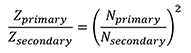
This allows a single component to serve two roles, thus reducing cost, footprint, and BOM.
Like transformers, baluns appear at first glance to be simple components, but in reality neither is simple. Baluns have important top-level RF parameters including frequency range, bandwidth, insertion loss, magnitude imbalance, phase imbalance, linearity, distortion, power rating, size, and cost. (These have the standard definitions with passive components, so there is no need to go through them here.) Note that some vendors specify bandwidth at the -1 dB point as well as the more-common -3 dB point; using the balun within the tighter 1 dB bandwidth will result in better performance, reduced distortion, and better linearity.
Despite the simple transformer-like topology of a basic balun, many other designs and configurations are possible and used in practice, determined by operating-parameter priorities, frequency and bandwidth, power level, available components, and cost. Note that not all applications require galvanic isolation in addition to the grounded/floating transformation; some baluns are used to provide the transformation but not isolation; one basic non-isolated one is somewhat analogous to an AC-line autotransformer (Figure 2).

Figure 2: A non-isolated balun can be built using a single winding, with a grounded center tap; the schematic is similar to the autotransformer used for adjusting AC powerline settings, but the design must have RF specifications.
As with most performance parameters, there are trade-offs and compromises that must be made when selecting a balun. For devices such as IoT units and single-band smartphones, the desired frequency of operation occupies a relatively narrow band, usually only a few percent of the nominal frequency. This simplifies the design of the balun and allows more flexibility in other parameter trade-offs. However, multiband smartphones, which must operate in separated bands, have a greater balun challenge. The solution there is to either use multiple, band-specific baluns, or a broadband balun which will likely have reduced linearity and flatness across the range of interest, along with higher insertion loss.
A single balun can usually meet the multiple design criteria of an application, in many cases. However, just as a multistage filter is sometimes needed in place of a simpler, single-stage filter in order to balance the trade-offs and compromises among design objectives, multiple baluns may be used in various configurations. Figure 3 shows an implementation which is used to achieve a wide passband, while Figure 4 shows a balun-type transformer which is pre-compensated to overcome magnitude and phase imbalances.

Figure 3: When a single balun and simple configuration cannot satisfy the multiple design objectives, two (or more) can be used in more complex configurations; here, two are used as a transformer-coupled input for a wideband A/D converter. (Courtesy of Analog Devices)

Figure 4: Another multi-balun configuration, again for a wideband A/D converter input, uses a compensated-balun type transformer in tandem with another balun.
Power rating for many applications is also low, and dissipation due to losses is not an issue. However, the balun specifications must be checked for peak-power handling as well as average capability, especially if the signal duty cycle is high, such as when transmitting large blocks of data as is done with advanced wireless protocols. Small wirewound baluns are available to handle these somewhat higher power levels with only a small increase in footprint and height compared to ceramic-based implementations.
Balun examples show diversity of lower-power designs
Baluns for power handling ratings on the order of hundreds and thousands of watts present serious current-handling and dissipation issues. They can be built of heavy-gauge wiring, tubing, or coaxial cable; specially-designed RF waveguides are used when the power level is in thousands of watts and the frequency is in a multi-GHz range.
Low-power applications have a very different physical scenario. For example, the MABA-007159-000000 from M/A-COM is a wirewound 1:1 RF transmission line balun/transformer for operation from 4.5 to 3000 MHz (Figure 5). It can handle up to 250 mW or 30 mA. Despite its simple schematic (Figure 6), it is an RF component and so must be characterized via RF parameters including insertion loss, input impedance (the venerable Smith chart), phase imbalance, and amplitude imbalance (Figure 7). Despite its non-monolithic construction, it is a surface-mount component with a small footprint of approximately 3.8 × 3.6 mm, and can be used with standard component-handling production equipment.

Figure 5: The M/A-COM MABA-007159-000000 uses a wirewound assembly approach to build a 1:1 RF transmission-line balun/transformer for wideband operation from 4.5 to 3000 MHz.

Figure 6: The schematic of the MABA-007159-000000 is indistinguishable from an AC-line or small-signal transformer.

Figure 7: Despite the simple schematic, M/A-COM provides a set of RF-performance graphs needed by designers using this wideband balun.
Other applications use integrated, monolithic baluns such as the STMicroelectronics BAL-CW1250D3, designed for 2400 MHz to 2500 MHz WLAN applications; it measures just 1.2 × 1.2 mm and is housed in a 5-bump flip-chip package. This 50 Ω input balun is specifically intended to match the ST-Ericsson RFIC CW1250, CW1150, CW1260 transceivers in their system configuration (Figure 8), and is fabricated using integrated-passive-device technology on a non-conductive glass substrate. As with the M/A-COM part, the vendor provides a full set of RF specifications, but here, they are only for the much-narrower bandwidth this device targets compared to the wideband M/A-COM device (Figure 9).

Figure 8: Built as a monolithic device, the narrowband STMicroelectronics BAL-CW1250D3 balun is designed to be a part of the BOM and interface of a specific set of ST-Ericsson transceivers.

Figure 9: Again, the vendor provides a comprehensive set of RF graphs, covering insertion loss, differential and single-ended return loss, amplitude and phase imbalance, and second-harmonic distortion.
Summary
The challenge of interfacing differential RF circuits to single-ended ones has been with the RF (and other) design community for many years. The balun (balanced/unbalanced) is a simple-looking passive component with an almost trivial schematic which resolves the challenge by transforming one signal configuration into the other, and can be used in either direction. A basic balun is a variation of a specialized RF transformer, and has many similarities to it; some systems have conflicting specifications which can be met with combinations of several baluns along with more complex topologies and interconnection configurations.
For more information about the parts discussed in this article, use the links provided to access product information pages on the DigiKey website.
Avertissement : les opinions, convictions et points de vue exprimés par les divers auteurs et/ou participants au forum sur ce site Web ne reflètent pas nécessairement ceux de DigiKey ni les politiques officielles de la société.

