Arduino OTA Updates Without an Arduino Cloud Account
2026-03-18 | By Maker.io Staff
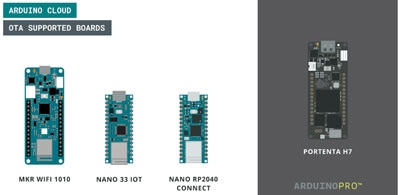
Over-the-air (OTA) updates are beneficial for managing IoT devices because they enable developers to roll out software updates without requiring physical access to the device. The Arduino Cloud offers a feature for the widely adopted Arduino platform. However, the platform requires users to create an account, and in some cases, purchase a paid subscription. Fortunately, there are ways to circumvent this limitation. This article demonstrates various approaches to OTA updates without an Arduino Cloud account.

What are OTA Updates
Over-the-air (OTA) updates deliver software improvements, such as additional features or critical security fixes, to devices wirelessly, usually over the Internet. OTA is common in mobile and IoT applications because it does not require physical access to the devices. The method further helps reduce downtime by updating multiple devices at once and without the need for user intervention.
As with any software update process, there is risk involved in OTA updates. For example, an update could result in a device becoming unreachable due to an error in the code or update procedure. Malicious actors could also gain access to the infrastructure and push harmful code to the devices. However, most of these risks can be controlled by following best practices.
Best Practices for OTA Updates
OTA updates should always follow a segmented rollout approach. This means that developers push updates to a small batch of easily-accessible nodes to check for errors before rolling them out to all devices. During this first phase, monitoring and testing are crucial, and developers must also plan for failures. It’s vital to include rollback and failsafe mechanisms that ensure nodes remain operational if errors occur.
Since OTA updates represent a potential attack vector, it’s important to employ mechanisms like code signing, authentication, encryption, verification, and rollback mechanisms in case of transmission or update errors.
The Two Common OTA Update Approaches
OTA updates commonly follow one of two basic workflows: push or pull. In the pull approach, the device periodically checks a remote server for updates by comparing its local version to the one provided by the server. If the server reports a newer version, the client requests the updated binary and stores it in a temporary location, such as Flash memory or an SD card. Once finished, the client calculates the checksum of the downloaded data and compares it to the one provided by the server, ensuring data integrity. If they match, the client moves the binary to its permanent storage, adjusts the boot address if necessary, and reboots using the new code.
In the push approach, the client exposes an interface that allows the update server or program to notify the client of a new version. The client can then download the binary from a trusted server and proceed with the update. Alternatively, the update server can directly push the updated binary to the client. The first strategy, in which the client downloads a new version when prompted, is more secure. This is because the binary comes from a trusted source. However, it requires an additional server that hosts the data. The second approach to push updates is more convenient, but the caveat is that the binary is not guaranteed to come from a trusted source.
In general, the pull approach offers better security, since the data comes from a trusted source. However, clients need to wake up periodically and check for updates, which can reduce the runtime of battery-operated projects. In contrast, the push approach offers more convenience, but may introduce additional security risks if developers are not careful.
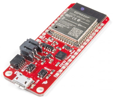
Pushing OTA Updates to ESP32 or ESP8266
ESP32 and ESP8266 devices are made for receiving OTA updates using the push method, since all required capabilities are baked into the standard firmware. Libraries can expose them to other platforms, such as Arduino. Examples include ESP8266HTTPUpdateServer, ESP32HTTPUpdateServer, ElegantOTA, and ArduinoOTA. All of these libraries allow pushing updates to the MCU over the Internet. ElegantOTA offers a straightforward web-based UI, and ArduinoOTA integrates the features into the Arduino IDE, enabling developers to upload software updates with a single click.
To set up ArduinoOTA, start by installing the ESP8266 or ESP32 board files, as described in this article. Then, add a header file that stores the Wi-Fi credentials and import it in the sketch together with the ArduinoOTA and wireless library for your board.
Store the secret values from the file in local variables, add two more constants that identify the board, and define a password needed for updating the firmware. Next, add two more variables that will be changed during one of the subsequent updates:
#include <WiFi.h> // Replace with your board's library (WiFiNINA.h, WiFi.h, Ethernet.h, ...)
#include <ArduinoOTA.h>
#include "arduino_secrets.h" // This file holds your WiFi credentials (SSID, PASS)

const char* ssid = SSID;
const char* password = PASS;
const char* boardName= "ESP_Client_1";
const char* otaPassword = "test";

float version = 1.0;
const int delayTime = 5000;
In the setup function, establish a network connection:
Copy Code
void setup() {
  Serial.begin(9600);

  Serial.println("Connecting to network...");
  WiFi.begin(ssid, password);
  while (WiFi.status() != WL_CONNECTED) {
    delay(500);
    Serial.print(".");
  }
  Serial.println("Done!");

  /* OTA setup (see below) */

  /* other setup code*/
}
Then, initialize the ArduinoOTA service in the setup function:
void setup() {
  /* WiFi setup code (see above) */

  Serial.println("Setting up OTA...");
  ArduinoOTA.setHostname(boardName);
  ArduinoOTA.setPassword(otaPassword);
  ArduinoOTA.begin();
  Serial.println("Done!");

  /* Other setup code */
}
These three lines are all that’s needed to start the service and make it run in the background. Finally, set up the IO ports and print the software version to have a visual confirmation of the code version that’s running on the board:
void setup() {
  /* WiFi setup code (see above) */

  /* OTA setup (see above) */

  Serial.println("Setting up IO...");
  pinMode(LED_BUILTIN, OUTPUT);
  Serial.println("Done!");

  Serial.print("Running version: ");
  Serial.println(version);
}
In this simple example, the loop function only toggles the built-in LED with a fixed interval. However, pay attention to the first line in the loop method. It tells the OTA service, started in the setup function, to check for incoming update requests before running the user code:
void loop() {
  ArduinoOTA.handle(); // This listens for update push messages!

  digitalWrite(LED_BUILTIN, HIGH);
  delay(delayTime);
  digitalWrite(LED_BUILTIN, LOW);
  delay(delayTime);
}
Upload the code via USB, as you normally would. Once the board reboots, check the serial console to verify that it has established a Wi-Fi connection. If the connection is established, the device should show up in the Arduino IDE as a new remote device in the port selection:
 The ESP8266 appears as a remote port in the Arduino IDE if ArduinoOTA was set up correctly.
You can then update the version number in the code and set a new blink interval to simulate changes in the software. However, ensure not to remove any of the OTA code. Each version of the code must always include the OTA setup code and handle() call to prevent losing remote access to the device after an update.
Once the step is completed, upload the updated version using the remote port. The IDE should ask you for the password you set earlier:
 The IDE asks for the password you set in the sketch before uploading.
Upon entering the password, the upload should proceed normally:
 Uploading can take a while, but it eventually finishes automatically.
Once the process succeeds, the board automatically restarts and runs the updated code. You can verify whether the update was successful by observing the LED or checking the new version number in the serial output:
 The ESP8266 reboots and prints the new version number to the console after receiving the OTA update.
Pushing OTA Updates to Arduino Boards
ArduinoOTA works with multiple official Arduino devices with networking capabilities. However, it’s not as straightforward to use as it is for the ESP32 or ESP8266, since the OTA capabilities are not baked into the board core files.
Start by installing the ArduinoOTA and the wireless library for your board, for example, WiFiNINA for the Arduino Nano 33 IoT. Then, change the OTA setup code from before to the following:
void setup() {
  /* WiFi setup code (see above) */

  Serial.println("Setting up OTA...");
  ArduinoOTA.begin(
    WiFi.localIP(),
    boardName,
    otaPassword,
    InternalStorage
  );
  Serial.println("Done!");

  /* Other setup code */
}
Next, you must copy a file from the ArduinoOTA library folder to the Arduino installation directory. Find the Arduino installation folder, which is typically located in the local AppData folder on Windows and the user library on Mac.
Then, find the SDK folder for your board in the packages directory. This folder should contain a platform.txt and programmers.txt file. Here is an example for the Arduino Nano 33 IoT:
 Find the correct folder for your board in the Arduino installation directory. It should contain the two highlighted files.
Create a new file, called platform.local.txt, in the same folder as the original platform.txt file from before:
 Add the new file to the same directory that already contains the platform.txt file. The result should look like this in the screenshot.
Open the newly created file and add the following contents:
tools.arduinoOTA.cmd={runtime.tools.arduinoOTA.path}/bin/arduinoOTA
tools.arduinoOTA.program.params.verbose=true
tools.arduinoOTA.program.params.quiet=
tools.arduinoOTA.program.params.t=60
tools.arduinoOTA.program.pattern="{cmd}" -address {ip} -password test -port 65280 -username arduino -sketch "{build.path}/{build.project_name}.bin" -upload /sketch -b
Make sure to adjust the password parameter if you used a different password in the Arduino sketch’s setup function. Save the file, open the original programmers.txt, and add the following contents to the end of it:
arduinoOTA104.name=Arduino OTA
arduinoOTA104.program.tool=arduinoOTA
arduinoOTA104.program.tool.default=arduinoOTA
arduinoOTA104.ip=192.168.1.103
Make sure to adjust the IP address to match your network configuration. Then, save the file and head back to the Arduino IDE. From the tools menu, select the option to reload the board data, and wait for the IDE to refresh.
Then, select the newly created Arduino OTA programmer from the tools menu:
 You can select the new OTA programmer after reloading the board data in the Arduino IDE.
You can push updates to the Arduino using the programmer from the sketch menu:
 Use the OTA programmer to upload the changes to the MCU.
Note that these instructions were tested with the Arduino Nano 33 IoT. Other boards may require different settings. Please refer to the library’s GitHub page for further details.
Summary
Over-the-air (OTA) updates refer to software updates that are rolled out to client devices over a wireless network. Developers can use them to add new features to devices and fix bugs. Developers should follow a few best practices, such as segmented rollouts and rollback mechanisms, to prevent losing access to the devices.
The push and pull strategies are the two main approaches to OTA updates. In the push method, the client exposes an interface to receive updates. In the pull approach, the client periodically checks for updates. Once the client learns about an update, it obtains the updated binary, checks for file integrity, and replaces the old program with the new version.
The ESP32 and ESP8266 are ideal devices for receiving OTA updates, since all necessary capabilities are baked into the standard firmware. Multiple libraries exist to leverage the OTA update features, and this article highlighted ArduinoOTA. You only need to add a few lines of code in the setup function and include a single handle() call in the loop to enable OTA update capabilities.
In addition, the ArduinoOTA library supports various official Arduino boards. However, the necessary steps are generally more involved than with Espressif MCUs. In the case of the Arduino Nano 33 IoT, you must place ArduinoOTA initialization code in the setup function and include the same handle() call in the loop. You may also need to change the board definition files and add a custom programmer in the Arduino installation folder for the IDE to detect the wireless port.